Gas Turbine Cascade Optimization
![]()
Constrained Optimization of Turbine Cascades with GA and SQP
I applied my GA based optimizer and my airfoil parameterization program to the design of a retrofit turbine cascade. This problem is more difficult than the standard airfoil optimization problem in that it is a highly constrained problem. In this project, I used 4 equality constraints and 1 inequality constraint. The objective was to find a shape that minimizes the total pressure loss across the cascade while satisfying the problem constraints. The resulting airfoil shape should provide a user specified lift, mass flow rate, exit flow angle, cross sectional area, and must have a thickness distribution greater than or equal to some specified minimum thickness distribution. Constraints were enforced using a combination of penalty functions and a sequential quadratic programming (SQP) code that was combined with my GA program. Each function analysis was performed with an unstructured finite volume transonic CFD code written by Professor Z-X. Han.
The optimizer was able to find a shape that nearly satisfies the constraints
(with 2.5% of the target values) as well as significantly improving the airfoil
efficiency. The animation below shows the best airfoil or each generation as it
evolves during the optimization process. One can see that the final shape
has a much weaker trailing edge shock wave that is the physical source of the
higher efficiency.
|
|
![]()
Constrained Multiobjective Optimization of Turbine Cascades with an Indirect Method of Optimization Based upon Self-Organization (IOSO)
This case is similar to the retrofit problem described above except I used a
multiobjective stochastic optimization code (IOSO) developed by Professor Igor
Egorov and modified by me to run on our parallel computer. The
objectives were to minimize the total pressure loss, maximize the total lift of
the row, and minimize the total number of airfoils for the row. For this
case I used an existing turbine airfoil, the VKI airfoil, as a baseline for
comparison. The goal is to use optimization to find an airfoil with greater
lift, higher pitch (fewer airfoils per row), and lower total pressure loss(more
efficient) that also has the same mass flow rate, exit flow angle, and cross sectional
area as the original VKI airfoil. All constraints were enforced using a penalty
method. Each function analysis was performed with an unstructured finite
volume transonic CFD code written by Prof. Z-X. Han. This problem was run
on our 32 processor parallel computer and consumed almost 30 hours of
computation time.
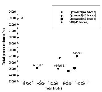
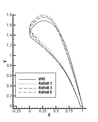
The IOSO optimization code generated a 3D pareto front composed optimal feasible solutions. The original VKI airfoil was not a member of this front. Cascade No.1 offers reduction of 7% in total pressure loss, needs 1 airfoil less than the VKI cascade, and generates about 1% higher total lift. Cascade No.3 offers reduction of 5% in total pressure loss, need 1 more airfoil than the VKI cascade, and generates about 6% higher total lift. Cascade No.6 offers reduction of 7% in total pressure loss, need the same number of airfoils as the VKI cascade, and generates about 4% higher total loading. The cascade No.1 may be the best compromise among three optimized cascades for many turbomachinery designs.
|
|
|
|
![]()